180o
RF Hybrid
by Michael Ellis
Copyright 2000, All Rights Reserved
| More Tutorials |
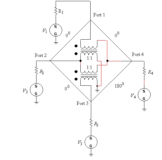
The 180o hybrid functions as a splitter/combiner for both 0o and 180o signals. You may download an analysis program that performs all the calculations described in this article. The 180o hybrid is usually represented as in figure 1 with the angles labeled along the sides. A signal into port 1 appears in-phase, 3 dB attenuated, at port 2 and port 4. No signal appears at port 3 therefore port 3 is said to be isolated relative to port 1.
A signal into port 2 appears in-phase at both ports 1 and 3, and isolated at port 4. Similarlly, a signal into port 3 appears in-phase at port 2 and 180o out-of-phase at port 4.

Figure 1. 180o hybrid
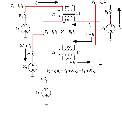
The 180o hybrid can be analyzed using the following steps.
1. If the current through R1 is defined as I1, then the voltage on the top of R1 is V1-I1R1.
2. The current through the secondary of T1 has to be the same as the primary current, I1.
3. The current through R4 is defined as I2.
4. The voltage on the top of R4 can be written in terms of I2 and is V4-R4I2.
5. The voltage across the secondary of T1 is the same as the difference in voltage
across the primary. The voltage is V1-I1R1-V4+R4I2.
6. The current through the secondary of T2 has to be I1+I2.
7. The voltage on the top of R3 can be written as the difference in voltage across the
secondary of T2 and is V1-I1R1-V4+R4I2-V4+R4I2.

Figure 2. 180o hybrid analysis
From figure 2, the current through R2 (which is 2I1+I2) can also be written in terms of the difference in the voltage across R2, or
| (1) |
Also the current through R3 (which is I1+I2) can be written in terms of the difference in voltage across R3, divided by R3, or
| (2) |
Rearranging equations (1) and (2) for solution of I1 and I2 yields
| (3) |
and
| (4) |
For analysis, only one of the voltages V1, V2, V3, or V4, will be non-zero at any given time. To calculate the impedance into port 1, let V1 = 1 and V2=V3=V4=0. The port 1 input impedance becomes
| (5) |
The other input impedances are
| (6) |
| (7) |
and
| (8) |
If R1, R2, R3, and R4 are set to 75 ohms, then Z1 = Z3 = 150 ohms and Z2 = Z4 = 37.5 ohms.