Inductance Measuring Circuit
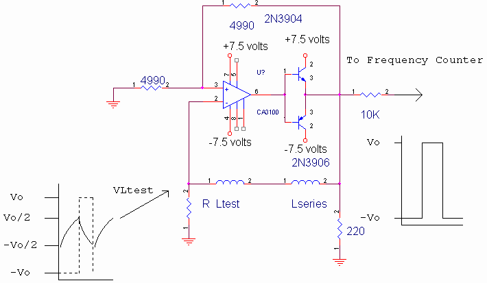
Inductor values from 1 henry to 1 microhenry can easily be measured with a frequency counter by using the oscillator circuit shown below. The output voltage at the emitters of the push-pull transistor pair alternatively charges and discharges the inductor under test (Ltest) through resistor R. When the voltage across R rises to ½ the output voltage, the output voltage reverses polarity, thus continuously repeating the cycle. The rate of charge, t, determines the frequency of oscillation which can be obtained from
![]()
Solving for Ltotal, and noting that t is ½ the period of oscillation, we obtain
![]()
where f is the frequency displayed on the frequency counter.
In order to obtain high accuracy at low values of inductance, a series inductor, Lseries, should be used to calibrate against the effects of non-ideal circuit performance. An inductor of 100 microhenries is recommended, although the exact inductance value does not matter. With Ltest replaced by a short, calculate Lseries from the equation
![]()
where f is the frequency displayed on the frequency counter.
Measurements of small values of inductance can therefore be made to within 1 microhenry using this equation. Other advantages to using a series inductance as a calibration inductance is that the circuit is guaranteed to oscillate for any value of test inductance (Ltest) and that the inaccuracies resulting from finite op-amp slew rate are cancelled out, even if the positive going slew rate differs from the negative going slew rate. The accuracy of measurement is in the order of 1% since 1% resistors are used to set the hysteresis voltage, however the measurement accuracy can be extended to 3 digits by hand selecting the precision resistors to within 0.1% and, if necessary, adding a microcontroller to interpolate between calibrated inductor values using a lookup table.
The 2N3906-2N3904 push-pull transistor pair is required because the CA3100T op-amp does not have enough current output to drive the low impedance feedback circuit consisting of Ltest and R. The 10K resistor buffers the circuit from the input capacitance of the frequency counter. The op-amp is powered by +/- 7.5 volts (instead of +/- 15 volts) to prevent excessive power dissipation in the circuit. The 220 ohm resistor is necessary to discharge the inductor during reversals in the polarity of the output voltage, otherwise a spike appears in the output voltage causing inaccuracies in the measured value of inductance. The circuit can be used with R=100 ohms, 1%, to measure inductance between 0.1 henry and 1 microhenry, or with R=10K for a range of 10 henries to 100 microhenries.
![]()
where
l = inductance in microhenries,
a = coil radius in inches,
b = coil length in inches,
N = number of turns.
For a desired inductance, l, the designer should calculate the number of turns, N, then wind an inductor with a few more than N turns, and gradually back off the number of turns, by measuring the inductance with the test circuit below until the exact inductance is achieved.

![]()
Return to 68HC11 Start Page