Capacitance Measuring Circuit
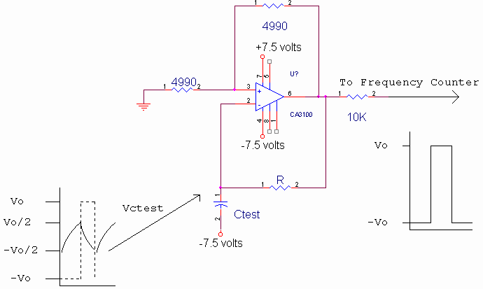
The simple oscillator circuit shown below produces an output frequency based on the value of the capacitance under test. As the voltage across the test capacitor changes through 2/3rds of the op-amp output voltage, the op-amp output reverses polarity, and the capacitor charges in the opposite direction. The rate of change, t, determines the frequency of oscillation which can be obtained from
![]()
![]()
Solving for Ctest, and noting that t is ½ the period of oscillation, we obtain
![]()
Where f is the frequency displayed on the frequency counter.
In order to obtain high accuracy at low values of capacitance, the op-amp stray input capacitance, Cinput, should first be measured as part of a calibration procedure using
With Ctest replaced by an open circuit. Measurements of small values of capacitance can therefore be made to within 1 pf using this method. It can also be shown that another advantage of subtracting Cinput from each measurement is that the effects of op-amp slew rate are cancelled, even if the negative going slew rate differs from the positive going slew rate.
The accuracy of measurement is in the order of 1% since 1% resistors are used in the circuit, however the measurement accuracy can be extended to 3 digits by hand selecting the precision resistors, and, if necessary, adding a microprocessor to interpolate between values using a lookup table.
The 10K resistor in the circuit below buffers the circuit from the input impedance for the frequency counter. The CA3100T op-amp should be operated at +/- 7.5 volts (instead of +/- 15 volts) to reduce changes in the op-amp input capacitance, Ctest, as a function of heat dissipation. The test capacitance should have one end tied to –7.5 volts (instead of ground) to make it possible to test electrolytics and other types of polarized capacitors. Values between 0.1 uf and 1 pf should use R = 499K, and values between 0.1 uf and 100 uf should use R = 4.99K.

![]()
![]()
![]()
![]()
![]()
Return to 68HC11 Start Page