0-15 Volt Tracking Power Supply
The linear dual tracking power supply, shown in the schematic, provides 0-15 volts, at 1/4 amp, maximum, using a discrete transistor regulator with op-amp feedback to control the output voltage. The supply was constructed in 1975; the negative ouput voltage tracks the positive output voltage.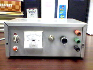
With reference to the schematic, lamp, LP2, is a power-on indicator. There is no adjustable current limiter in this unit, although R1, D2, and D3 set the current limit to approximately 0.25 amps on the positive side, and R15, D9 and D10 set the current limit to slightly greater than 0.25 amps on the negative side. The voltages at the output of Q1, and Q3 are pre-regulated to 20 volts so that the op-amp supply voltages do not exceed the maximum supply ratings for these op-amps. R9, R12 and U2 cause the negative supply to track the positive output voltage. R7 is a front panel potentiometer to adjust the output voltage(s). 
Download the Orcad Schematic File
A more modern circuit might use a single IC regulator, such as the MC78XX, or MC79XX series, immediately after the full wave rectifier, to replace approximately 20 components, or at least a high precision zener diode to replace D5 as the voltage reference. The LM4040 is one such voltage reference and has excellent stability over temperature. IC regulators such as the MC78XX series may eventually become obsolete as newer IC regulators are designed, however, discrete transistors, op-amps, and zeners are more generic, have a longer production lifespan, and allow the designer to demonstrate that he understands the principles of linear regulated power supply operation.
Copyright 1999, Mike Ellis, All Rights Reserved
Home
You are visitor number 
