An Adjustable 4/9:1 - 9:1 Impedance Transformer
| More Tutorials |
The 9:1 Impedance Transformer
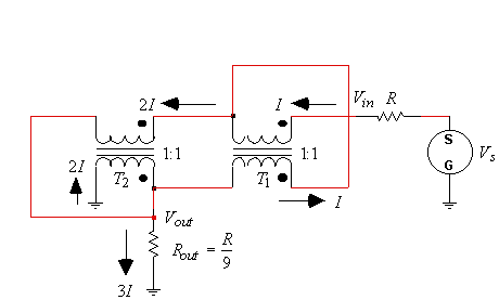
In figure 1, a voltage source, Vs, will produce an input voltage, Vin, and an input current, I. For a 1:1 turns ratio, the current induced in the secondary of T1 is also be equal to I. These two currents add to produce 2I flowing through the primary of T2, which induces a secondary current of 2I in transformer T2. The current flowing through the load resistor is therefore 3I. In an ideal situation, the transformer network can be assumed to be lossless; therefore, the output power must equal the input power. The input power is given by
![]() (1)
(1)
The output power is
![]() (2)
(2)
For the input power to equal the output power, then
![]() (3)
(3)
If R is defined such that
![]() (4)
(4)
then the correct termination output impedance should be given by Vout/3I, or
![]() (5)
(5)

Figure 1. A 9:1 impedance transformer using 1:1 transformers.
The 4/9:1 Impedance Transformer
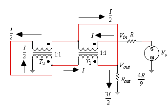
By simply moving the termination resistor, Rout, from the secondary of T2, to the secondary of T1, a 4/9:1 impedance transformation can be realized. Again, if the input current is designated as I, then the current through the secondary of T1 has to be equal to I. Since T2 is also a 1:1 turns ratio, the primary and secondary currents of T2 must be equal. By Kirchhoff's current law, these two currents add to produce the current I flowing in the seconday of T1; therefore the currents through the primary and the secondary of T2 are equal to I/2. Again by Kirchhoff's current law, the current through Rout must be 3I/2. Assuming lossless transformers for the sake of solving for the proper termination impedances, if the input power must equal the output power, then
![]() (6)
(6)
or
![]() (7)
(7)
The proper output termination, Rout, becomes,
 (8)
(8)

Figure 2. A 4/9:1 impedance transformer using 1:1 transformers.